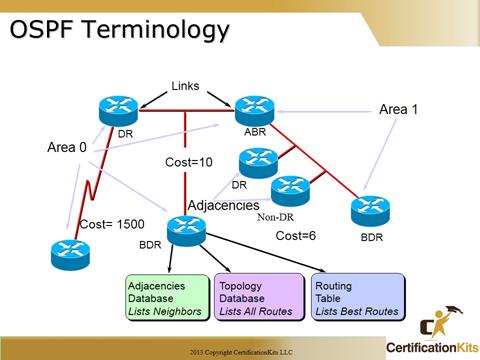
Link – Interface on a router
Link-state – Status of a link between two routers
Includes a router’s interface and its relationship to its neighboring routers
Cost – Indication of the overhead required to send packets across an interface
High bandwidth = low cost
Area – A contiguous grouping of networks and routers sharing the same Area ID and topology database
DR (Designated Router) – An elected router in Broadcast and Non-Broadcast environments that is adjacent to all other OSPF routers
BDR (Backup Designated Router) – An elected router in Broadcast and Non-Broadcast environments that is adjacent to all other OSPF routers that will promote it self if the Designated Router is no longer available
Neighborship Database – Listing of all the neighbors to which a router has established bi-directional communication
Link State/Topological Database – List of information about all other routers in the same area
Routers in the same area have identical link state databases
Routing Table – Generated when the SPF algorithm is run on the link-state database
Each router has a unique routing table
Neighbor – Two routers that have an interface on a common network
Usually discovered by hello’s but can also be configured administratively
Adjacency – Relationship formed between selected neighbors in which routing information is exchanged. Not all neighbors are adjacent
Only Broadcast and Non-Broadcast network types have Designated and Backup Designated Routers!!!
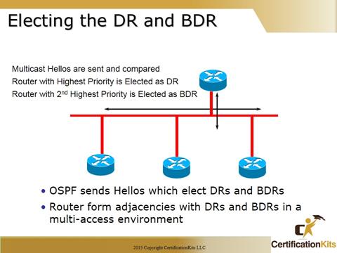
- •Elected routers that coordinate the flow of route updates within a subnet
- • All routers on a sub-net form adjacencies with the DR and BDR
- • Clients send updates to the DR and BDR only
- • The DR informs all other clients of changes in topology
- • BDR assumes DR role if DR fails but performs no DR functions if DR remains available
- • It is generally not a good idea to select the same router to be designated router on many LANs simultaneously.
- • ONLY Broadcast and Non-Broadcast Network types have Designated and Backup Designated Routers.
The following outlines the process OSPF takes and rules that are followed when electing a Designated Router:
- • Routers elect a DR and BDR per network
- • All routers set by default to priority 1 (0-255)
- • Priority of zero (0) means router can not be elected as a DR
- • Router with highest priority wins BDR (1 – 255), if no other router has a higher priority the BDR will then become the DR
- • RouterID breaks tie, Router ID is either the Highest Loopback or Highest Configured IP address on any given active interface
- • If DR fails, BDR promoted to DR and a new BDR is elected
- • Existing DR will not be overthrown if “better” router is turned on after initial election
- • DRs and BDRs listen to multicast traffic on both multicast address 224.0.0.5 and 224.0.0.6 224.0.0.6 is exclusively listed to by DRs
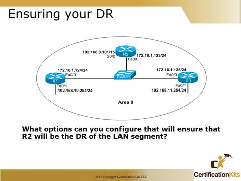
First, what is the RID of each router? Which router is the default DR for the 172.16.1.0 LAN?
There are three options that will ensure that R2 will be the DR for the LAN segment 172.16.1.0/24:
- Configure the priority value of the Fa0/0 interface of the R2 router to a higher value than any other interface on the Ethernet network.
- Configure a loopback interface on the R2 with an IP address higher than any IP address on the other routers.
- Change the priority value of the Fa0/0 interface of R1 and R3 to 0. A priority of 0 causes a router to not be eligible to be a DR.
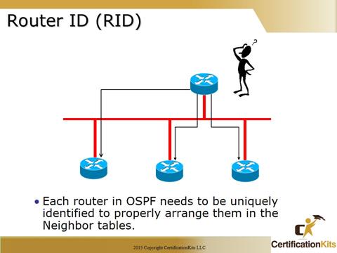
Each router that is participating in OSPF needs to be uniquely identified. The method of identification that OSPF uses is Router IDs (RID).
32 bits that uniquely identifies an OSPF router
Highest IP address in router is RouterID
Overridden by Loopback interface if present
Even if Loopback address has lower value
Recommended to use loopback interface
Easier to manipulate this number
Always up
Interface loopback 0
Ip address 10.1.1.1 255.255.255.0
You can also Statically assign the Router ID in the OSPF router configuration mode:
(config)# router ospf 1
(config-router)# router-id
Do NOT use same loopback address on different routers
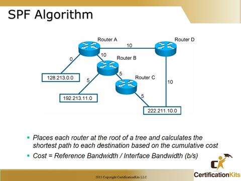
The SPF algorithm places each router at the root of the tree and calculates the shortest path to each node utilizing the Dijkstra’s algorithm. It is based on the cumulative cost required to reach each node. The cost is based on bandwidth. The default reference bandwidth is 10 to the 8th, which is 100,000,000 or the equivalent of the fast ethernet which means a fast ethernet has a default cost of 1. A 10Mb/s ethernet has a default cost of 10 and so on. Due to the increased speeds of networks today (i.e. 1Gbs and 10Gbs) the reference bandwidth can be changed so that a 1Gbs link would be more desirable than a 100Mbs link.
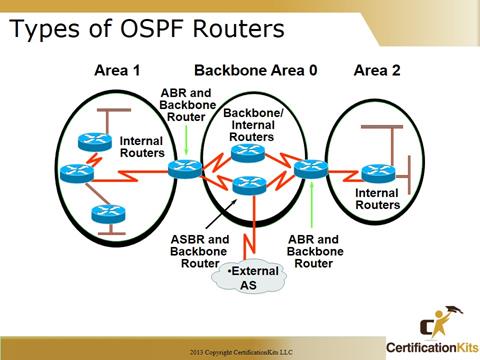
Notice how each router connects to the backbone—called area 0, or the backbone area.
OSPF must have an area 0, and all non-zero areas must connect to this area (an exception is when using a virtual link which is not covered in this course). Non-zero areas are connected to the backbone area (area 0) through Area Boundary Routers (ABRs). Still, at least one interface of a router must be in area 0.
OSPF runs inside an autonomous system, but can also connect multiple autonomous systems together. The router that connects these AS’s together is called an Autonomous System Boundary Router (ASBR).
Area 0 is called the backbone area
Hierarchical OSPF networks do not require multiple areas but do support them
Non-zero OSPF areas must connect to area 0 via an Area Boundary Router
Internal Routers: All interfaces reside inside same area
Area Border Routers: One interface in each of two areas
Backbone Routers: At least one interface resides in Area 0
AS Boundary Routers: One interface resides in a non-OSPF area
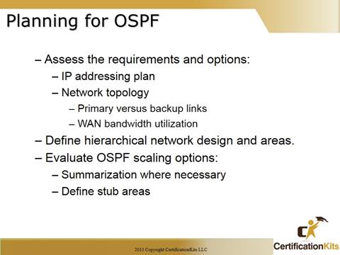
Since OSPF is hierarchical in nature, coming up with an OSPF design to include not only an IP Address plan but also defining OSPF areas to include types in key. As such, OSPF implementation depends on the specific needs and topology. When planning an OSPF design you must gather information about your topology. Examples are as follows:
- • IP Address usage.
- • Network topology (e.g. Connected links)
- • Design of multiple OSPF areas as it makes sense.
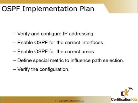
Once you has compiled your requirements, it is time to create an Implementation Plan. Key pieces developing an Implementation Plan are as follows:
- • Define IP Networks that need to be included (advertised) by OSPF.
- • Enable OSPF on the correct interfaces or with the correct network statement under the OSPF routing process
- • Verify OSPF is enabled within the correct area
- • Specify any metrics if you want to change the default behavior of OSPF.
- •After implementation is complete, verify everything is working as expected.
In addition to all the normal documentation associated with implementing and deploying a routing protocol, documenting OSPF area is essential.

