Topologies
Point-to-Point
Two sites are connected with other. Each site maintains a dialer interface and maps to other site’s telephone numbers. Mulitple link can also be bundled to provide additional bandwidth using multi-link PPP (MLPPP). Figure-1 depicts P2P topology.

FIGURE-1: P2P DDR Connections
Fully Meshed
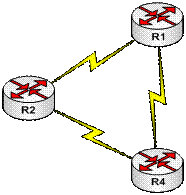
Recommended for small DDR networks. Allows any-to-any connectivity. However, the trade-off is configuration complexity since each site must maintain mapping for other sites. Additional bandwidth can also be made available if more links are provisioned between sites using MLPPP.

FIGURE-2: Full-Mesh
Hub and Spoke
Figure-3 depicts the hub and spoke topology. It is the easier to configure as compared to full mesh. Spoke dials to hub (in this case R1) and hub dials-out to relevant spoke site.

FIGURE-3: DDR Hub and Spoke
All the configuration complexities can easily be managed, since only hub maintains the relevant mapping information to spokes. Additional bandwidth can be provided by allocated multiple links between hub and spokes MLPPP. Redundancy can be achieved by providing multiple hubs. Scalability can be achieved with Multi-Chassis MLPPP. If any-to-any connection behavior is required, split horizon (for distance vector protocols) must be disabled on hub router.
Dialer Profiles (DP)
Dialer profiles separate logical configuration from the physical interface. Because of this separation, multiple dialer profile configuration can share the interface such as ISDN, asynchronous modems or synchronous serial connections. Dialer Profiles bind the logical and physical configuration together dynamically on-call basis. DP can define encapsulation, ACLs, minimum and maximum call etc… for the actual physical interface. Typical usage is bound one physical B channel to another dialer profile and while other B channel bound to anther DP. This allows the same physical interface to used simultaneously for different calls.
There is another method called the dialer maps. It is legacy configuration method for DDR and is not discussed in this document.
Components of Dialer Profiles
Figure-1 depicts the relation ship between dialer profile components.

FIGURE-1: Dialer Profile Components
Dialer interfaces
Logical entities that use a per-destination dialer profile. You can create any number of dialer interfaces in a router. All configuration settings specific to the destination go in the dialer interface configuration. Each dialer interface uses a dialer pool, which is a pool of physical interfaces (ISDN BRI and PRI, asynchronous-modem, and synchronous serial).
Dialer pool
Each interface references a dialer pool, which is a group of physical interfaces associated with a dialer profile. A physical interface can belong to multiple dialer pools. Contention for a specific physical interface is resolved by configuring the optional priority command.
Physical interfaces
Interfaces in a dialer pool are configured for encapsulation parameters. The interfaces are also configured to identify the dialer pools to which the interface belongs. Dialer profiles support PPP and High-Level Data Link Control (HDLC) encapsulation.
Dialer map-class (optional)
Supply configuration parameters to dialer interfaces (for example, ISDN speed, dialer timers’ parameters, and so on). A map-class can be referenced from multiple dialer interfaces. Out of scope of this tutorial.
Configuration
1. Define Intresting Traffic
Step-1: configure terminal
Step-2: dialer-list ip permit
2. Create Dialer Interface and associating to dialer pools
Step-1: configure terminal
Step-2: interface dialer
Step-3: ip address
Step-3: encapsulation
Step-4: dialer remote-name
Step-5: dialer string
Step-6: dialer-pool
Step-7: dialer-group
3. Configure and associate physical interface to dialer group
Step-1: configure terminal
Step-2: interface
Step-3: dialer pool-member
Example: Consider Figure-2 for details. R1 and R2 are connected with a leased line (T1 connection). To provide redundancy, ISDN links are provisioned between these two site. All IP traffic is allowed and ISDN will only be used if the T1 connection is not available. R2 has a network 172.16.2.0/24 attached to its LAN segment and R1 has 172.16.1.0/24 attached to its LAN segment. R2 is the spoke site and R1 is the head office. Static routing is used with primary route via leased line and back route through ISDN BRI.

FIGURE-2: ISDN DDR as Backup
| |
|
| |
! interface BRI0 |
