Neighbors
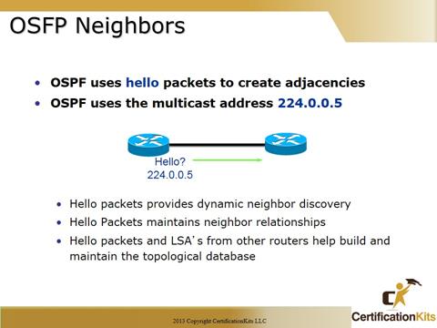
Neighbors are two or more routers that have an interface in a common network, such as two routers connected on a point-to-point serial link.
Adjacency
An adjacency is a relationship between two OSPF routers that permits the direct exchange of route updates. OSPF is really picky about sharing routing information, unlike EIGRP that directly shares routes with all of its neighbors.
Instead, OSPF directly shares routes only with neighbors that have also established adjacencies.
Link State Advertisement
A Link State Advertisement (LSA) is an OSPF data packet containing link-state and routing information that’s shared among OSPF routers.
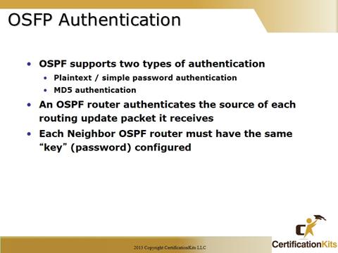
OSPF neighbor authentication can be configured such that OSPF routers must agree on predefined passwords prior to exchanging OSPF information.
OSPF routers authenticate the source of each routing update packet that it receives. Authentication comes in two flavors, either plaintext / simple or MD5 authentication. The authentication is accomplished by the exchange of an authenticating key that is known by both the sending and receiving router.
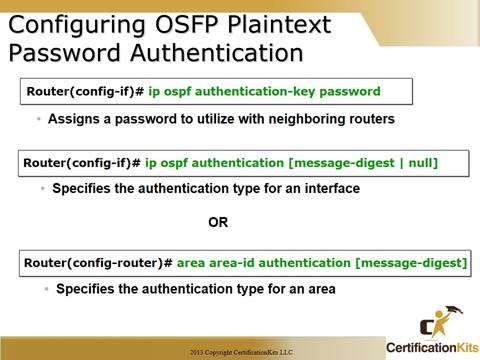
Example OSPF Plaintext Password Authentication configuration:
interface Serial0
ip address 192.16.64.2 255.255.255.0
ip ospf authentication-key kal
!— The Key value is set as “kal”. It is the password that is sent across the network.
!
router ospf 10
log-adjacency-changes
network 70.0.0.0 0.255.255.255 area 0
network 192.16.64.0 0.0.0.255 area 0
area 0 authentication
!— Plain text authentication is enabled for all interfaces in Area 0.
Configuring MD5 authentication is similar. Under the interface configuration the following command would be utilized:
ip ospf message-digest-key 1 md5 kal
Under the router ospf 10 the following would be utilized:
area 0 authentication message-digest
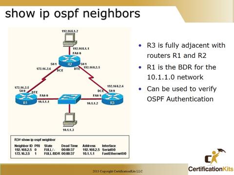
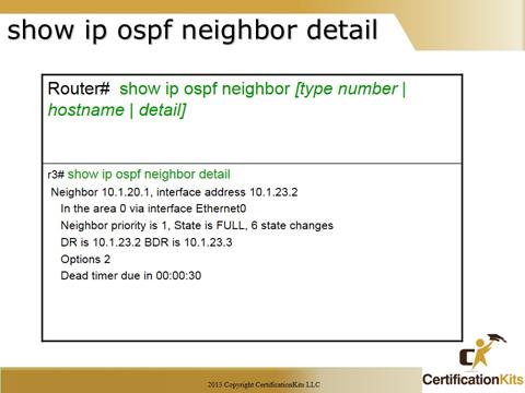
The show ip ospf neighbor command displays OSPF relevant information about OSPF neighbors.
As you can see from the output on the slide, fields that are displayed are as follows:
ID – Router ID of the OSPF neighbor
Priority – OSPF priority of the OSPF neighbor
State – Displays the state of the OSPF router. Is it a DR, BDR, etc.
Dead Time – Expected time before Cisco IOS software will declare the neighbor dead.
Address – Actual address of the interface the OSPF router is assigned.
Interface – Interface the neighbor is learned on.
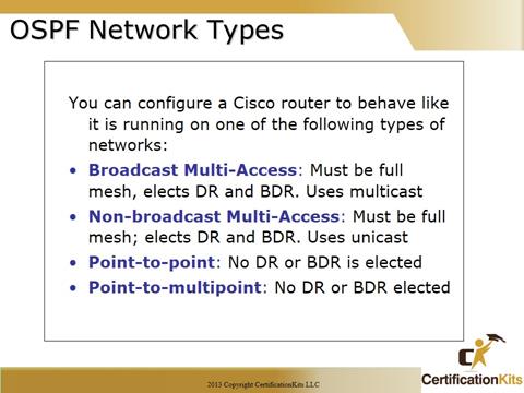
Broadcast (multi-access)
Broadcast (multi-access) networks such as Ethernet allow multiple devices to connect to (or access) the same network, as well as provide abroadcast ability in which a single packet is delivered to all nodes on the network. In OSPF, a DR and BDR must be elected for each broadcast multi-access network.
Nonbroadcast multi-access
Nonbroadcast multi-access (NBMA) networks are types like Frame Relay, X.25 and Asynchronous Transfer Mode (ATM). These networks allow for multi-access, but have no broadcast ability like Ethernet. So, NBMA networks require special OSPF configuration to function properly.
DR and BDR are elected on broadcast and nonbroadcast multi-access networks
Point-to-point
Point-to-point refers to a type of network topology consisting of a direct connection between two routers that provides a single communication path. The point-to-point connection can be physical, as in a serial cable directly connecting two routers, or it can be logical, as in two routers that are thousands of miles apart, yet connected by a circuit in a Frame Relay network. In either case, this type of configuration eliminates the need for DRs or BDRs.
Point-to-multipoint
Point -to-multipoint refers to a type of network topology consisting of a series of connections between a single interface on one router and multiple destination routers. All of the interfaces on all of the routers sharing the point-to-multipoint connection belong to the same network. As with point-to-point, no DRs or BDRs are needed.
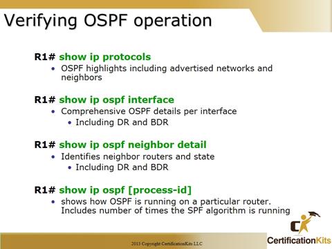
There are several ways to verify proper OSPF configuration and operation, and this slides shows some basic verification commands.
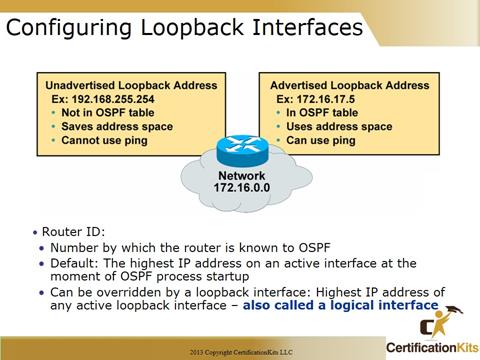
Each router that is participating in OSPF needs to be uniquely identified. The method of identification that OSPF uses is Router IDs (RID).
32 bits that uniquely identifies an OSPF router
Highest IP address on a router is the RouterID
Overridden by Loopback interface if present
Even if Loopback address has lower value
Recommended to use Loopback interface
Easier to manipulate this number
Always up
Interface loopback 0
ip address 10.1.1.1 255.255.255.0
You can also Statically assign the Router ID in the OSPF router configuration mode:
(config)# router ospf 1
(config-router)# router-id
Do NOT use same loopback address on different routers
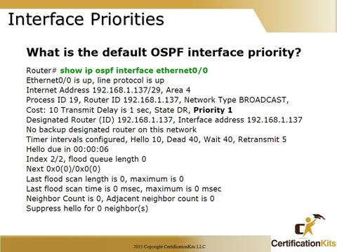
Sometimes it is desirable for a router to be configured so that it is not eligible to become the DR or BDR.
You can do this by setting the OSPF priority to zero with the
ip ospf priority priority <#> (interface subcommand)
Router(config-if)# ip ospf priority {0 – 255}
Change the priority of a router on an interface
0 means to not participate in election
1 is default, 255 is highest priority
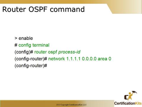
ROUTER OSPF process-id:
-Enables the OSPF routing process
-Process-id identifies a specific instance of the OSPF program – locally significant only
-Multiple OSPF process instances can be running simultaneously but this is not recommended
NETWORK address wildcard-mask AREA area-id:
-Enables the OSPF routing process on an interface
-Must specify either a specific ip address of an attached interface or a network to which one or more interfaces are attached
-Every network must be associated with an area that can be specified in decimal or dotted-decimal notation. For stability, no one router should belong to more than 3 areas.
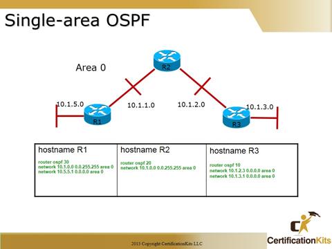
The example above depicts a simple single area implementation with three routers using area 0.
Let’s move on and evaluate the output of each of these commands.
The show ip protocols command also gives you many of the OSPF parameters such as filters, default metric, maximum paths, and the number of areas configured on a router.
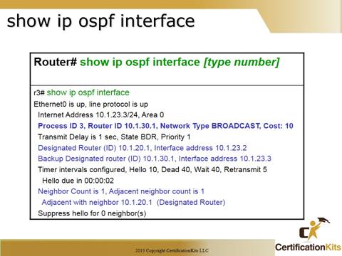
There are several commands that a network administrator can use to verify OSPF. The show ip ospf interface command is used to identify which interfaces are currently participating in OSPF.
- • Cost associated with OSPF interface
- • Designated Router information
- • Number of Neighbors known on your Link (Network, Interface)
- • Number of Adjacent neighbors
The show ip ospf neighbor command will identify:
- • Discovered Neighbors
- • Interfaces those Neighbors are located on
- • Priority of Neighbors
- • Designated Router information
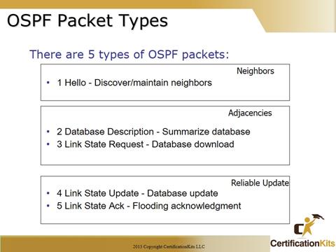
1 Hello – Discover/maintain neighbors
2 Database Description – Summarize database
3 Link State Request – Database download
4 Link State Update – Database update
5 Link State Ack – Flooding acknowledgment
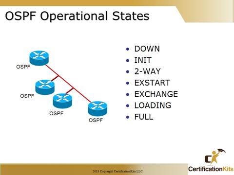
DOWN – no recent information received
INIT – a hello packet has been seen
2-WAY – neighborship has been established
— election for DR/BDR may now occur —
EXSTART – first phase of adjacency establishment – DR/BDR asserts it’s authority
EXCHANGE – DR sends DBDs to client, may request LSAs from client
LOADING – DR asks for most recent LSAs
FULL – links state databases are synchronized
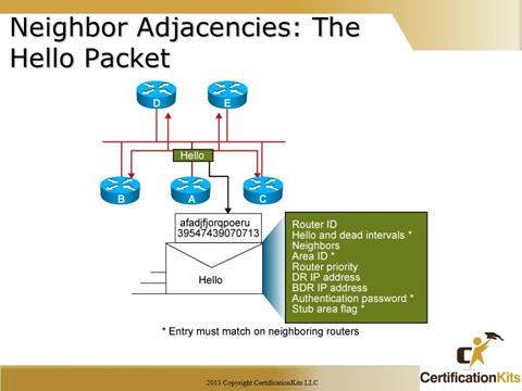
Hello packets are utilized by OSPF routers to recognize each other in order to share information. Each interface participating in OSPF sends hello packets multicast periodically to 224.0.0.5. The entries in the figure with an “*” much match between adjacent routers or a neighbor relationship will NOT be established. These include Hello and dead intervals, Area ID, Authentication password (if used) and Stub area flag.
Each hello packet sent from an OSPF router will contain:
Router ID (RID) ****Must be unique****
Subnet Mask
Priority Number ****0 means cannot participate in election****
Timer Value (Hello) ****This number must match for all neighbors, if not OSPF will not form a relationship with that peer!****
Neighboring (on same segment) Router ID’s
This is the information your OSPF router will use during the OSPF elections.
The frequency of the hello packets can be modified, however if one router modifies the timer interval, all OSPF routers in that network must modify their timers to match.
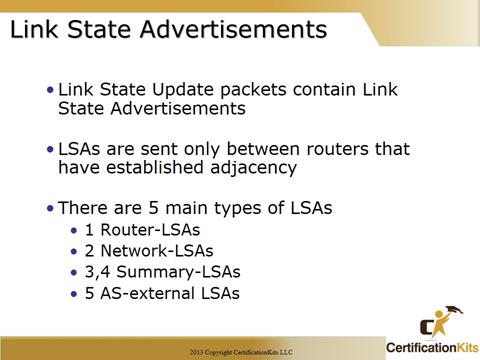
Type 1:Router Link Advertisement
- • Generated by each router for each area to which it belongs
- • Describes the states of the router’s links to the area.
- • Flooded within entire area
Type 2: Network Link Advertisement
- • Generated by DR in multi-access network
- • Describe the set of routers attached to a particular network
- • Flooded within entire area
Type 3 & 4:Summary Link Advertisement
- •Originated by ABRs
- •Flooded though out backbone area
- •3 describes routes to networks within the local area
- •4 describes routes to ASBRs
- •Not flooded to totally stubby areas
Type 5: AS External Link Advertisement
- •Originated by the ASBR
- •Describes routes to destinations external to the autonomous system
- •Flooded everywhere except stub and totally stubby areas
Type E1 entries add the internal OSPF cost to the seed metric as the external route propagates through the network – preferred behavior
Type E2 entries do not add internal OSPF costs – default behavior. Assumption is that routing between AS represents the major cost and that the path cost inside a single AS is trivial in comparison
Cisco CCNA Neighbor Adjacencies: The Hello Packet
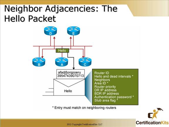
Hello packets are utilized by OSPF routers to recognize each other in order to share information. Each interface participating in OSPF sends hello packets multicast periodically to 224.0.0.5. The entries in the figure with an “*” much match between adjacent routers or a neighbor relationship will NOT be established. These include Hello and dead intervals, Area ID, Authentication password (if used) and Stub area flag.
Cisco CCNA SPF Algorithm
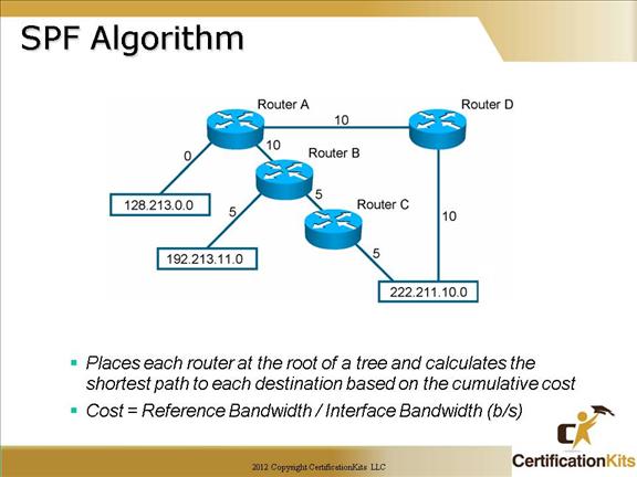
The SPF algorithm places each router at the root of the tree and calculates the shortest path to each node utilizing the Dijkstra’s algorithm. It is based on the cumulative cost required to reach each node. The cost is based on bandwidth. The default reference bandwidth is 10 to the 8th, which is 100,000,000 or the equivalent of the fast ethernet which means a fast ethernet has a default cost of 1. A 10Mb/s ethernet has a default cost of 10 and so on. Due to the increased speeds of networks today (i.e. 1Gbs and 10Gbs) the reference bandwidth can be changed so that a 1Gbs link would be more desirable than a 100Mbs link.
Cisco CCNA Types of OSPF Routers
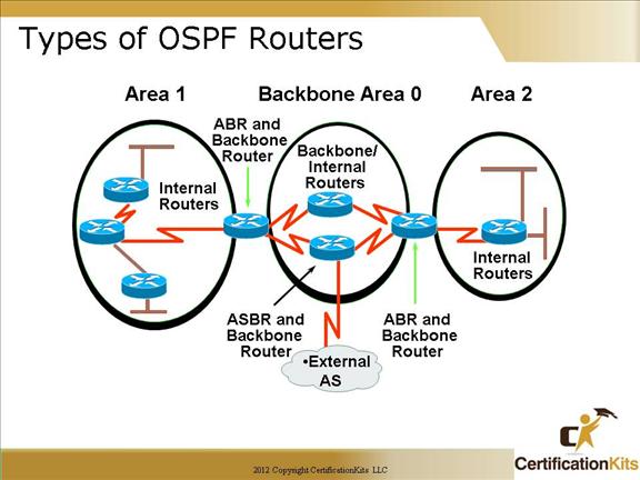
Notice how each router connects to the backbone—called area 0, or the backbone area.
OSPF must have an area 0, and all non-zero areas must connect to this area (an exception is when using a virtual link which is not covered in this course). Non-zero areas are connected to the backbone area (area 0) through Area Boundary Routers (ABRs). Still, at least one interface of a router must be in area 0.
OSPF runs inside an autonomous system, but can also connect multiple autonomous systems together. The router that connects these AS’s together is called an Autonomous System Boundary Router (ASBR).
Area 0 is called the backbone area
Hierarchical OSPF networks do not require multiple areas but do support them
You must have an area 0
Non-zero OSPF areas must connect to area 0 via an Area Boundary Router
Cisco CCNA OSPF Concepts
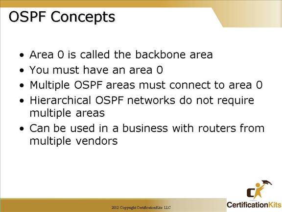
Area 0 is called the backbone area
You must have an area 0
Multiple OSPF areas must connect to area 0
Hierarchical OSPF networks do not require multiple areas
OSPF is standards based so it can inter-operate with routers from other vendors
Process ID’s can be assigned any number from 0 to 65535. Unlike an Autonomous System (AS) in EIGRP, Process ID’s can be different on each router and still communicate.
Area’s can be any number up to 2.4 billion and can even be displayed as an IP address if you wish.
Cisco CCNA Configuring a Single Area OSPF
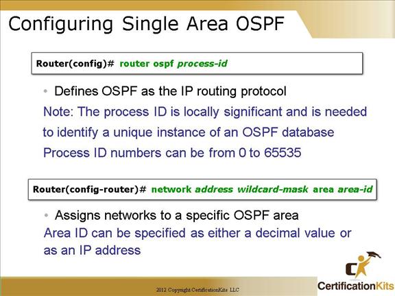
Configuring basic OSPF isn’t as simple as RIP, IGRP and EIGRP, and it can get can really complex once the many options that are available within OSPF are factored in.
Two basic elements of OSPF configuration are:
-Enabling OSPF
This is accomplished with the “router ospf process-id” command.
-Configuring OSPF areas
This is accomplished with the “network address wildcard-mask area area-id” command.
The easiest, and also least scalable way to configure OSPF is to just use a single area. Doing this requires a minimum of two commands.
router ospf
A value in the range 0 – 65535 identifies the OSPF Process ID.
network address mask area area-id
The area-id should be 0 if only a single area is configured.
Cisco CCNA OSPF Configuration Example
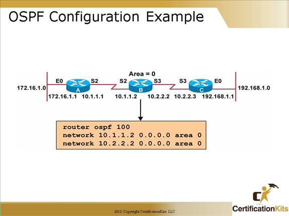
After identifying the OSPF process, you need to identify the interfaces that you want to activate OSPF communications on, as well as the area in which each resides.
This will also configure the networks you’re going to advertise to others. OSPF uses wildcards in the configuration. In the example the wildcard mask utilized on both network statements was 0.0.0.0 which means match exactly as a 0 in the bit position means match exactly while a 1 in the bit position means match anything. For example a wildcard mask of 0.0.0.255 means match the first three octets exactly and the fourth octet can be any value.
Cisco CCNA Example 2
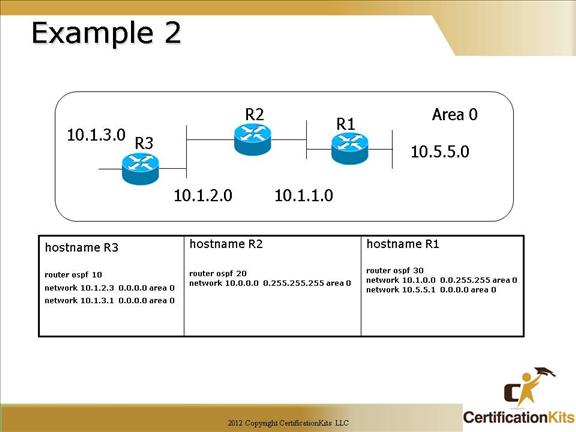
There are various ways to configure OSPF.
The configuration of R3 shows how the 0.0.0.0 wildcard is used to place each interface individually into area 0
R2 show how two interface can be configured into area 0 with one wildcard network statement of 0.255.255.255
R1 shows the wildcards of 0.0.255.255 and 0.0.0.0
It doesn’t matter how you configure the network statements, the results are the same.
Remember, the process ID is irrelevant and can be the same on each router, or different on each router, as they are in this example.
Cisco CCNA Verifying the OSPF Configuration
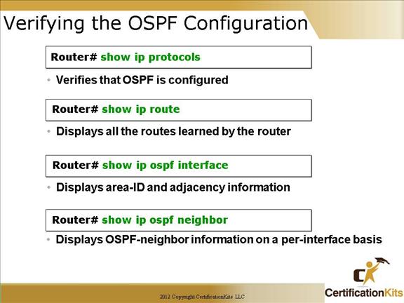
There are several ways to verify proper OSPF configuration and operation. Some of the commands are as follows:
show ip protocols: This command is useful in debugging routing operations. Information in the Routing Information Sources field of the show ip protocols output can help you identify a router suspected of delivering bad routing information.
show ip route or show ip route ospf: Displays the current state of the routing table
show ip ospf interface: Displays general information about Open Shortest Path First (OSPF) routing processes.
show ip ospf neighbor: Displays OSPF-neighbor information on a per-interface basis.
OSPF is great if you configure it properly. Now let’s look at other ways to do that.

