Cisco CCNA The OSI Reference Model
Early development of networks was chaotic for numerous reasons. The OSI reference model was created to simplify internetwork connectivity and speed time to market. The OSI reference model breaks the network hierarchy into seven layers. These layers will be explored in detail in this chapter.
Cisco CCNA The OSI Reference Model
The OSI reference model was created in the late 1970s, and the main reason the International Organization for Standardization (ISO) released the OSI model was so different vendor networks could work (communicate) with each other.
One of the greatest functions of the OSI specifications is to assist in data transfer between disparate hosts, meaning, they enable us to transfer data between a Unix host and a PC or a Mac, for example.
The OSI isn’t a physical model, though. Rather, it’s a set of guidelines that application developers can use to create and implement applications that run on a network.
It also provides a framework for creating and implementing networking standards, devices, and internetworking schemes.
Cisco CCNA OSI Layer & Functions
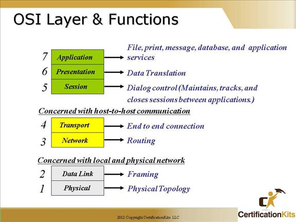
The OSI reference model has seven layers:
Application layer – The spot where users actually communicate to the computer.
Presentation layer – Presents data to the Application layer and is responsible for data translation and code formatting.
Session layer – Responsible for setting up, managing, and then tearing down sessions between Presentation layer entities.
Transport layer – Segments and reassembles data into a data stream.
Network layer – Manages devices addressing, tracks the location of devices on the network, and determines the best way to move data.
Data Link layer – Provides the physical transmission of the data and handles error notification, network topology, and flow control.
Physical layer – Sends and receives bits.
Cisco CCNA OSI Model (Rational)
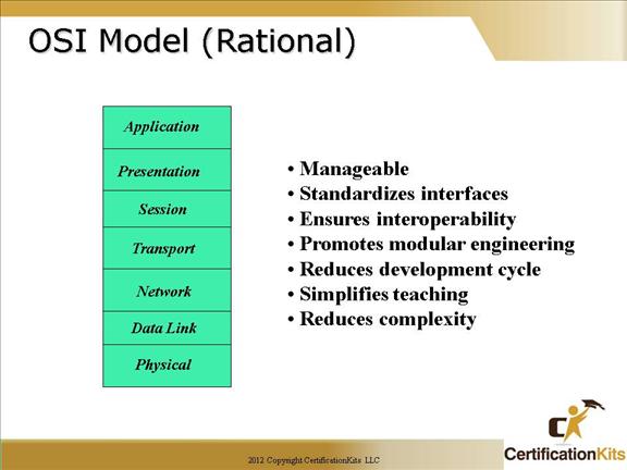
Early network development was chaotic. The early 1980s saw tremendous increases in the number and sizes of networks. By the mid-1980s, companies began to experience difficulties from all of the expansions they had made. It became more difficult for networks using different specifications and implementations to communicate with one another.
To address the problem of networks being incompatible and unable to communicate with one another, the International Organization for Standardization (ISO) researched different network schemes. As a result of this research, the ISO created a model that would help vendors create networks that would be compatible with, and operate with, other networks, hence the OSI reference model.
The OSI reference model was released in 1984. It provided vendors with a set of standards that ensured greater compatibility and interoperability between the various types of network technologies produced by companies around the world. The OSI model is considered the best tool available for teaching people about data networks.
Cisco CCNA OSI Model (Remembering)
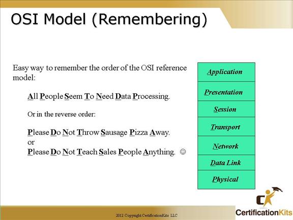
Sentences to help remember the layers of the OSI Reference Model:
All People Seem To Need Data Processing.
Or
Please Do Not Throw Sausage Pizza Away.
Or
Please Do Not Teach Sales People Anything.
Cisco CCNA Application Layer
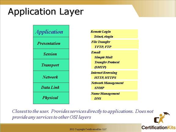
The Application layer (also called Layer 7) of the OSI model marks the spot where users actually communicate to the computer.
This layer is responsible for identifying and establishing the availability of the intended communication partner, and determining if sufficient resources for the intended communication exist.
A vast array of protocols combine at the DoD model’s Process/Application layer to integrate the various activities and duties spanning the focus of the OSI’s corresponding top three layers (Application, Presentation, and Session).
Cisco CCNA Presentation Layer
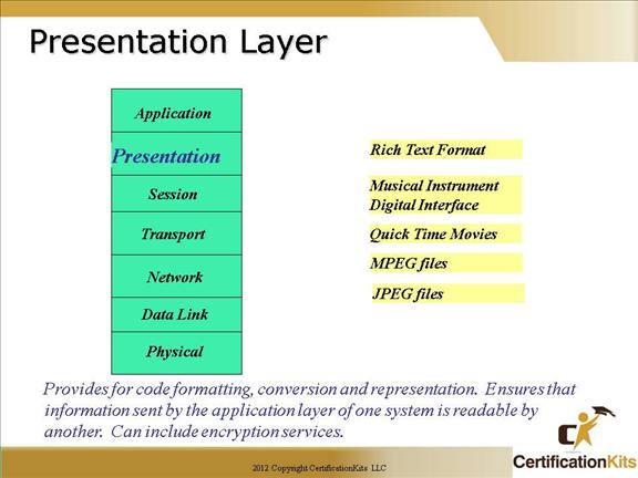
The Presentation layer (also called Layer 6) gets its name from its purpose: It presents data to the Application layer and is responsible for data translation and code formatting.
This layer is essentially a translator and provides coding and conversion functions. A successful data-transfer technique is to adapt the data into a standard format before transmission.
Cisco CCNA Session Layer
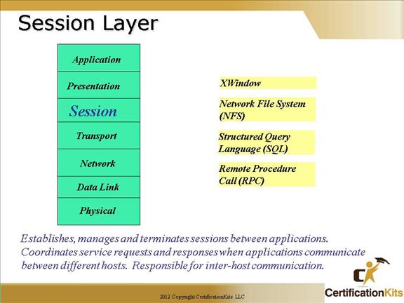
The Session layer (also called Layer 5) is responsible for setting up, managing, and then tearing down sessions between Presentation layer entities.
This layer also provides dialogue control between devices, or nodes.
Cisco CCNA Transport Layer
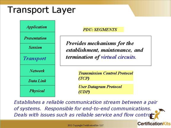
The Transport layer (also called Layer 4) segments and reassembles data into a data stream.
Services located in the Transport layer both segment and reassemble data from upper-layer applications and unite it onto the same data stream.
They provide end-to-end data transport services and can establish a logical connection between the sending host and destination host on an internetwork.
Provides mechanisms for the establishment, maintenance, and termination of virtual circuits.
The Transport layer can use positive acknowledgement and retransmission to ensure reliable delivery.
Information flow control.
The Transport Layer sends Segments between peer transport layers.
Cisco CCNA Network Layer
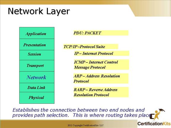
The Network layer (also called Layer 3) manages devices addressing, tracks the location of devices on the network, and determines the best way to move data, which means that the Network layer must transport traffic between devices that aren’t locally attached.
Routers (layer-3 devices) are specified at the Network layer and provide the routing services within an internetwork.
Device addressing
Tracks locations of devices on the network
Determines the best way to move data
PDU at the Network layer is called “Packet”.
The Network layer sends Packets between peer network layers.
Cisco CCNA Data Link Layer
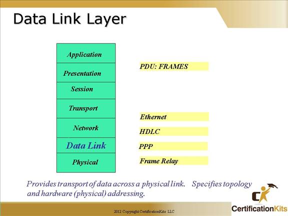
The Data Link layer (also called Layer 2) provides the physical transmission of the data and handles error notification, network topology, and flow control.
This means the Data Link layer will ensure that messages are delivered to the proper device on a LAN using hardware addresses, and translates messages from the Network layer into bits for the Physical layer to transmit.
The Data Link layer sends Frames between peer data link layers.
Cisco CCNA Physical Layer
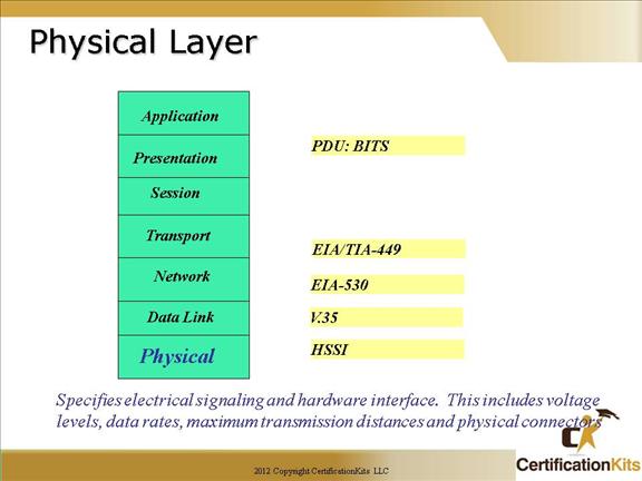
Finally arriving at the bottom, we find that the Physical layer (also called Layer 1) does two things: It sends bits and receives bits. Bits come only in values of 1 or 0—a Morse code with numerical values.
The physical layer defines the electrical, mechanical, procedural and functional specifications for:
activating
maintaining
deactivating
the physical link between end systems.
The Physical layer sends Bits between peer physical layers.
Cisco CCNA Data Encapsulation
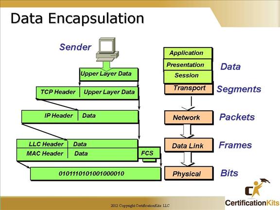
Data Encapsulation is utilized when data is transmitted from the application layer to the physical layer of the OSI reference model.
Following the data stream on the figure above:
Alphanumeric user input is converted to data for transmission on the network (At the upper layers)
Data is converted to segments, which allow hosts to reliably communicate (At the Transport Layer)
Segments are converted to packets or datagrams with a source and destination logical address (At the Network layer)
Packets or datagrams are converted to frames for transmission over an interface to the network (At the Data Link Layer)
Frames are converted to bits, and uses a synchronization and clocking function (At the Physical Layer)
Again, data encapsulation occurs when going from layer 7 to layer 1 of the OSI reference model.
Cisco CCNA Data De-Encapsulation
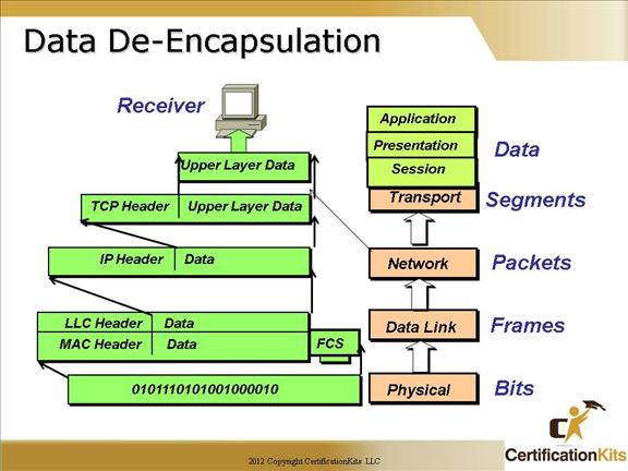
Data De-Encapsulation is utilized when data is transmitted from the physical layer to the application layer of the OSI reference model.
For Data De-Encapsulation the reverse data stream (as compared to data encapsulation) happens:
Bits are converted to frames and sent to the Data Link Layer
Frames are converted to packets or datagrams and sent to the Network Layer
Packets are converted to segments and sent to the Transport Layer
Segments are converted to data and sent to the Transport Layer
Data is converted to alphanumeric output for users at the Application Layer
Again, Data De-Encapsulation occurs when going from layer 1 to layer 7 of the OSI reference model.
Cisco CCNA Peer to Peer Communication
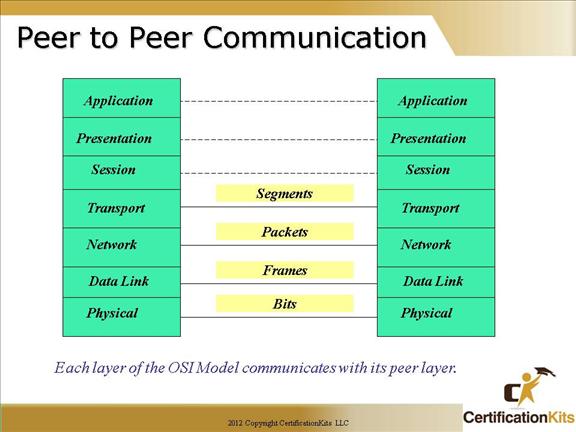
Each layer of the OSI model at the source must communicate with its peer layer at the destination. During the protocols at each layer exchange packets of information called protocol data units (PDUs) between peer layers.
Bits are sent between physical layer peers.
Frames are sent between data link layer peers.
Packets are sent between transport layer peers.
Segments are sent between transport layer peers.
Cisco CCNA TCP/IP Stack compared to OSI
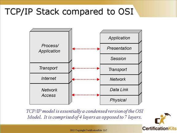
The TCP/IP model is basically a condensed version of the OSI model—it’s composed of four, instead of seven, layers:
Process/Application layer
Transport layer
Internet layer
Network Access layer
The OSI model and the TCP/IP stack were developed, by different organizations, at approximately the same time as a means to organize and communicate the components that guide the transmission of data.
